Around 2006 I heard for the first time about an amplifier linearization technique called DPD (Digital Pre-Distortion). It has been widely utilized in the mobile phone industy.
Although the possibility of adopting DPD technique for amateur equipments has been discussed among technically inclined amateurs on some reflectors and other places, I have not seen any actual report of experiments or implementation.
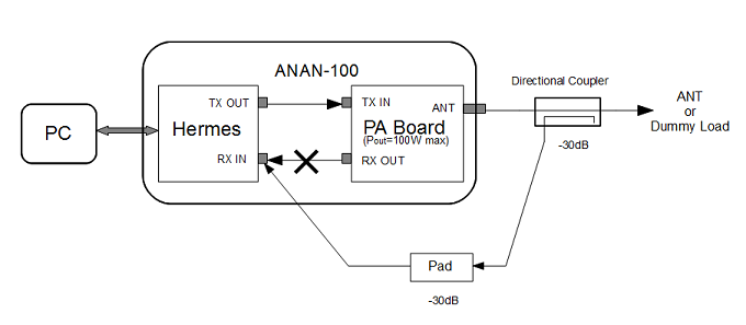
The test setup is shown in the figure below.

Experimental Setup for DPD
To tap the TX output signal I inserted a directional coupler at TX output and an addional attenuator (20dB or 30dB) is used to adjust the level for monitoring my own transmitting signal. The ANAN has its own receive-only antenna connectors but the isolation between RX and TX ports of the ANAN-100 is not good enough to monitor transmitting signal in such a way. As some people mentioned on the Yahoo group the amount of isolation is around 60dB. I temporarily removed the coax cable of RX path between the PA board and the Hermes and fed the tapped signal directly to the RX port of Hermes. I was unwilling to drill a hole in the panel of my ANAN so I used the hole for the 10MHz external ref. connector for the direct connection to the Hermes' RX port. I get more than 100dB isolation with that configuration.
You need to add an additional relay if you want normal transceiving operation though you would still miss the HPFs and 6m LNA for RX placed on the ANAN PA board.
As a software environement, I'm using GNU Radio libraries and tools and the GNU Radio block for Hermes developed by N5EG.
A number of methods have been proposed and employed for digital predistorion. My experiment is based on a simple LUT based method. It first measures the AM-AM and AM-PM characteristics of the target amplifier by using a test signal. Then a LUT that contains information about gain and phase deviation with respect to input signal amplitude levels. The predistorter compensates the amplitude and phase of the input samples by using the table and send the resulting samples to the exciter.
I have not tried implementing automatic calibration function during TX.
In order to measure the characteristics of the power amplifier a sine wave is used whose amplitude is ramped up in 100 steps. It starts at the amplitude of 0.01 and goes up to 1.0. I'm not sure what is the best way to ramp up or what is the best number of steps. The TX drive level of Hermes is set so that the ANAN produces 100W when the input signal amplitude reaches 1.0.
I managed to get the AM-AM and AM-PM characteristics of my ANAN-100's PA and the following graphs show those characteristics. Y-axis represents relavive input level(-40dB to 0dB). 0dB corresponds to the input amplitude of 1.0 where the output power reaches 100W. X-Axis represents variations of gain and phase respectively.
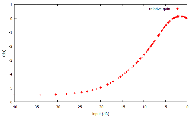
AM-AM characteristics of the ANAN-100's PA @14MHz(Max Pout=100W)
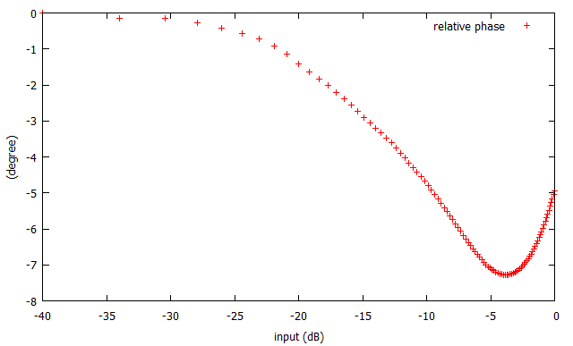
AM-PM characteristics of the ANAN-100's PA @14MHz(Max Pout=100W)
From the above data a LUT (LookUp Table) is constructed. The baseband 2-tone signal is predistorted using the table and fed to the ANAN-100. The 2-tone signals are 700Hz and 1900Hz.
The examples of output spectrum are shown in graphs below.
Updated 2013.Jul.10th
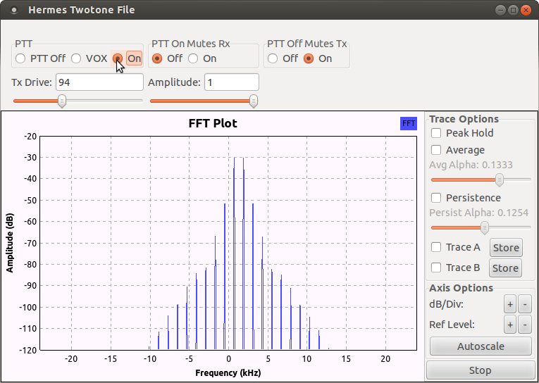
IMD @ 14MHz/30W PEP without predistortion
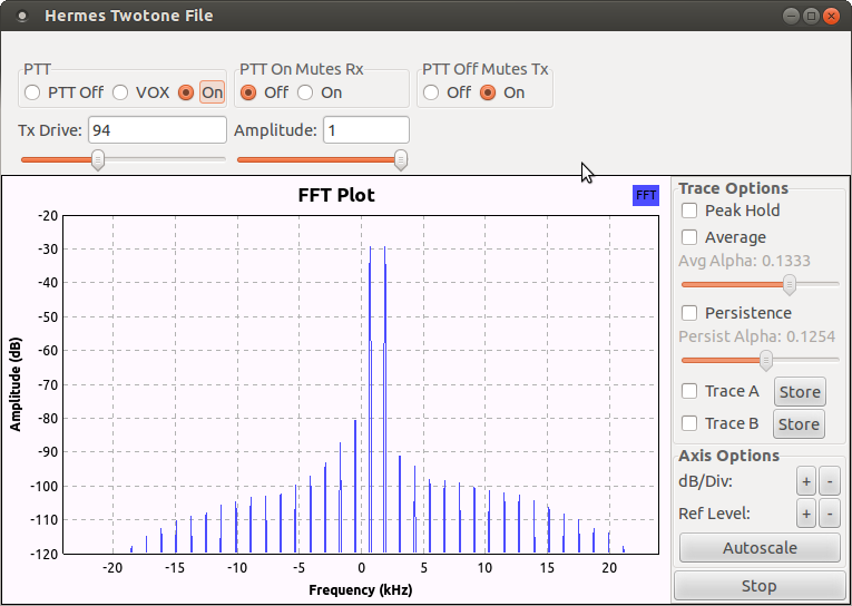
IMD @ 14MHz/30W PEP with predistortion
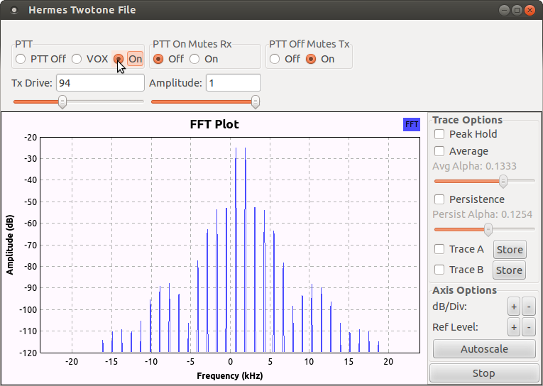
IMD @ 14MHz/100W PEP without predistortion
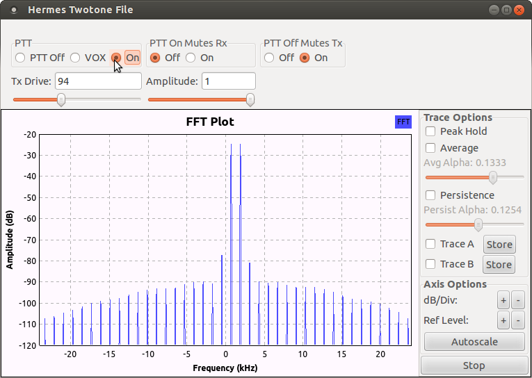
IMD @ 14MHz/100W PEP with predistortion
The result seemed fairly good for the very first attempt or at least interesting. Lower order IMDs were reduced almost 30dB while higher order ones were somewhat increased.These graphs shown above are at 14MHz but I got similar results on 3.5MHz and 21MHz bands. The characterization of the PA and the constrution of the LUT has to be done for each band.
This is the very first dpd experiment for me. There are many things I would like to do. For example: