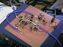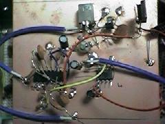
Some of my receivers have 455kHz IF output and the maximum sampling rate of my sound card is 48kHz. So I built a converter that translates 455kHz IF signal into another lower IF like commercial DSP radios (TS950, IC756 etc). I chose 12kHz as the lower IF frequncy. The translated signal is then applied to the soundcard.

The converter is simple. It consists of a local oscillator(1 transistor), a balanced mixer(MC1496) and a buffer amplifier (TL072). It was built in dead-bug style.


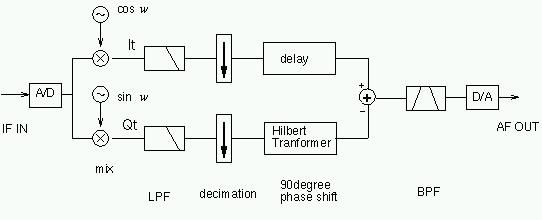
The 455kHz IF signal is down-converted to 12kHz and fed to the soundcard. The signal is then converted into 16bit signed integer value by the soundcard. The sampling rate is 48kHz. The processing hereafter is done by PC's main CPU (400MHz Celeron in my case).
The sampled 12kHz signal is multiplied by 2 carriers which are 90 degree different in phase from each other. In this case because the carrier signal is 12kHz which is exactly 1/4 of the samplig frequency, the two time-series of numbers such as, {1,0,-1,0,1,0,....} and {0,1,0,-1,0,1,....} represent the required carriers. So the computation becomes very simple. The resultant signals are a in-phase(I) signal and a quadrature(Q) signal.
After that as the maximum frequency of the signal is under 3-4kHz the sampling rate can be reduced. This sampling-rate reduction is called decimation. I chose the lower sampling rate of 12kHz, so just throw away 3 samples out of 4. But the bandwidth must be limited before decimation to avoid aliasing. A low pass filter, which need not be very sharp, is inserted.
Next, one of the two signals will be 90 degree phase-shifted. That's a difficult task in the analog world but it can be achieved relatively easily with a hilbert transformer in the digital world.
Finally I and Q signals are added(LSB) or subtractd(USB) and you will get the demodulated signal.
The following band pass filter is the final selective filter. I don't use one currently.
The resultant signal(represented in integers) are sent back to the D/A converter on the soundcard and then translated into AF output you can hear.
An example of demodulated signal:
NHK(domestic broadcast of R.Japan 9550kHz,USB)(wav file)
Yt = sqrt (It^2 + Qt^2)The output Yt may be passed through a HPF to filter out the DC component.
An example of demodulated AM signal
BBC World Service(21660kHz)(wav)
I implemented the same thing by software. Just set the output sound device to stereo(2 voices) mode and send I/Q signal to L/R channel respectively.