SSB generation
SSB signals can be generated by the process that is reverse of the
demodulation. Signal from MIC is sampled at 12kHz rate and filtered
by a pair of FIR filters. The two filters have exactly the same
frequency response in amplitude but their phase response are 90 degree
different from each other.
Then resultant two signals are interpolated to 48kHz sampling rate
and mixed with carrier of 12kHz. Finally take the sum or difference of
two signals and a 12kHz LSB(or USB) signal will be produced.
I made an up-converter which translates a 12kHz SSB signal at the
soundcard output into the IF frequency of FT747 tranceiver(8.2158MHz).
I have only worked one local station yet but according to
his report my DSP setup sounds very good.
Up converter
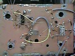
The upconverter is simple, too. An SBL-1 diode DBM for mixer,
one Tr. for X'tal osc and another Tr. for output buffer.

IC at left is MC1496(not used). At right you can see SBL-1.
At lower center is Lo circuit.
Modification to FT747

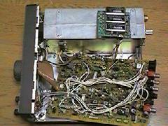
- In FT747 the DSB output from balanced modulator IC(upc1037H) connected to
the crystal filter is switched by two diodes. I cut the line
which gives 9V to these diodes during transmission. Actually I
unsoldered and raised the TX9V-end of 220 ohm resister (R146) from
the board. Solder new lead to the resister and TX9V line respectively
and these two leads werer connected to the additional outboard switch.
- Connect the output of homebrew upconverter to the input terminal
of the crystal filter board thourgh additional diode switch.
TX9V line for the diode switch is also connected to the above mentioned
outboard switch. You can select internal generator or DSP generator
by the switch.
- When the DSP generator is used I set 747 to
AM mode so that the signal is passed through AM filter(6KHz BW).
License
In Japan every change to the station setup(modification,
addition/deletion of equipments or whatever) must be reported to the
official and granted permission. I wrote the block diagram
of FT747, upconverter and the software and sent them to the office.
It took more than one month to receive permission.
Frequency Response
I mesured the frequency response of overall setup.
Audio frequency generator was connected to the soundcard and the power
meter to the FT747 output.
First set the generator freq to 1kHz and output power to 10W.
Then change the freq of the generator signal from low-end to
around 4kHz and read how the output power changed.
The -3dB bandwidth(where the output power was more than 5W) was
150-3000Hz.
source codes available.


